TECH ARTICLE 01 – CONFIGURING AUDIO SYSTEM LIMITERS
Configuring audio system limiters properly requires an understanding of speaker driver power handling and how power amplifiers operate in regards to that power handling.
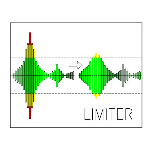
PURPOSE OF A VOLTAGE LIMITER
A voltage limiter is a dynamic control element in the signal path that modifies the change in signal level above a user-defined level with the purpose of protecting speaker drivers from mechanical or thermal damage. These limiters are usually present on each frequency band output on system processors and are used to limit the signal level for each frequency band independent of the other bands.
The effectiveness of a voltage limiter in protecting a speaker driver is highly dependent on properly setting the threshold of the limiter, which is the level above which the limiter will modify the level or rate of change of the signal. Since we are only controlling the signal level going into the amplifier, we must have a way to calculate the power being dissipated in the speaker driver given some known quantities. We will need to know the gain of the amplifier and the impedance of the load.
THE GAIN OF AN AUDIO POWER AMPLIFIER
An audio power amplifier is a block in the signal chain whose purpose is to increase a signal’s amplitude by a linear multiplication factor. This increase in level is necessary to be able to dissipate power in the speaker driver to create electro-motive force. When a load is placed across the output of the amplifier, the amplifier must also be able to provide enough current to maintain that voltage across the load. Because the amplifier is increasing both the voltage and current capability of the signal, it is referred to as a power amplifier.
We call the amount of increase in the signal voltage from input to output of the amplification stage the “gain” of the amplifier. The gain is a constant, linear multiplication factor that is the same across all frequencies, and it is common to use the logarithmic unit of the decibel when working in the audio domain.
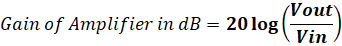
Where Vin equals the input voltage and
Vout equals the output voltage.
If a signal that swings +/- 1 Volt is doubled by an amplifier stage to swing +/- 2 Volts, then the gain of the amplifier would be 20log (2/1), or, roughly, 6dB. If the amplification stage increases the signal voltage amplitude by a factor of ten, then the gain of the stage is x10, or 20log(10/1) = 20dB. Most modern professional audio power amplifiers have a gain of 32dB which is roughly x40.
POWER DISSIPATED IN THE SPEAKER DRIVER OR LOAD
A power amplifier does not create or send power. A power amplifier produces a voltage across its output terminals and then provides the current necessary to maintain that voltage across a load. In this manner, a “1,000W amplifier” is not always “sending” 1,000 Watts, but rather, it has the capability of maintaining an output voltage across a load by providing enough current to maintain that voltage and, ultimately, power is dissipated in the load up to 1,000W.
If the voltage across the load and the impedance of the load are known then the power dissipated in the load can be calculated according to the following common equation:

Where P is the power dissipated in the load,
V is the voltage across the load and
Z is the impedance of the load.
V is the output voltage of the amplifier, which is the input voltage of the amplifier times the gain of the amplifier, and Z is the impedance of the load.
Thus, if we control the voltage of the signal going into the amplifier, we can control the power being dissipated in the load. We control the signal level going into the amplifier using a limiter. In this manner, a signal limiter does not “limit power” directly, but rather, it limits the signal voltage presented to the amplifier input and is often referred to as a voltage limiter.
LIMITER ATTACK AND RELEASE TIMES
Since we’re considering a dynamic signal, we need to also be aware of the attack and release times of a limiter. The attack time is the speed at which the limiter forces the signal voltage to meet the level defined by the ratio of the limiter. The release time of the limiter is the speed that the signal is allowed to return to its un-limited level once the signal is below the threshold. Since the gain change created by a limiter is a type of signal-related distortion, it can be very noticeable if the attack and release time constants are not set properly.
Fast attack and release are often associated with limiters that are meant to limit the peaks of a signal, while slow attack and release are related to controlling the average level of a signal. High peak levels may cause mechanical damage to a driver as the travel of the cone exceeds the limitations of the adhesives and materials of the driver. High average levels translate to increased temperature of the driver which can cause failure by melting or deformation of the former
Fortunately, most modern digital voltage limiters have the ability to set the attack and release times automatically according to the lowest frequency that is being sent through the limiter.
Peak and average
CALCULATING THE LIMITER SETTINGS
The easiest way to determine a threshold setting for a limiter is to take the specified power handling of a driver and the impedance of the driver, and enter those values into a standard limiter threshold calculator such as can be found at
www.Funktion-One.com/calculators
The alternative is to do the calculations by hand, which is beneficial to help fully understand how the settings are arrived at.
VOLTAGE THRESHOLD VS dBu THRESHOLD
Some processor platforms use dBu for threshold setting units and some use voltage. Based on the information above, it should be apparent that these are, effectively, interchangeable. The voltage threshold point is the output voltage of the amplifier, which is related, in dBu, to the input voltage through the gain of the amplifier. Proper on-line calculators will show you both voltage and dBU settings.
FIELD TAKEAWAYS
Integrators:
1. Always confirm amplifier gain, driver power ratings and driver impedance before setting thresholds.
2. Use limiter threshold calculator or calculate directly the proper settings.
3. Always use automatic time constants
Designers: Specify limiter strategy (RMS + peak), not just “limiter enabled.”
Acousticians: Expect tonal drift over time if thermal behavior is ignored.

